Guide on Establishing Communication Between HMI-PLC and PLC-INVT VFD
GUIDE FOR ESTABLISHING COMMUNICATION BETWEEN HMI – PLC AND BETWEEN PLC – INVT VFD
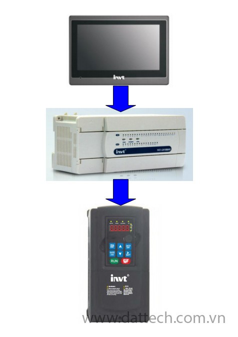
Note: Use Port 0 of the PLC for communication with the HMI and Port 1 of the PLC for communication with the INVT VFD using Modbus RTU protocol.
Step 1: Create a Simple PLC Program to Control the VFD Start/Stop and Set Speed Through HMI
1.1. Configure Communication Parameters on Port 0 (Communication with HMI):
In the AutoStation software, go to Project Manager -> System Block -> Communication Port.
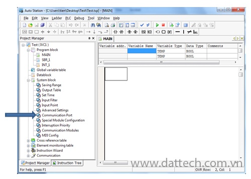
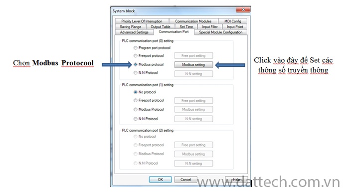
A tab labeled “Communication Port” will appear. Under “PLC Communication Port (0)” settings, do as shown in the image:
A Modbus Protocol window will appear. Choose parameters like Baud rate, Data bit, Stop bit, Parity check, and Station no. For “Master/Slave mode,” make sure to select “Slave Station” (PLC is always a Slave, while the HMI is the Master. Port 0 of the PLC is used for communication with the HMI).
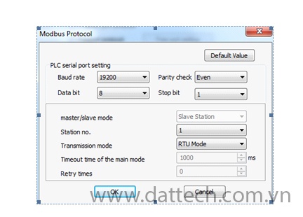
After making the selections, click OK
Note: The Baud rate, Data bit, Stop bit, Parity check, and Station no. settings in AutoStation must match those in VT-Designer (VT-Designer is the HMI programming software).
1.2. Configure Communication Parameters on Port 1 (Communication with VFD):
Also in Project Manager -> System Block -> Communication Port
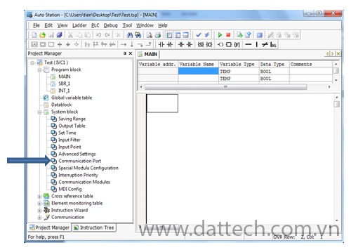
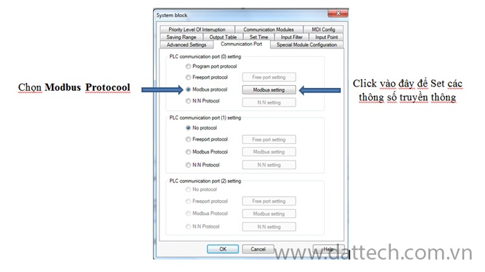
Tab Communication Port, under “PLC Communication Port (1)” settings, do as shown in the image:
A Modbus Protocol window will appear. Choose parameters like Baud rate, Data bit, Stop bit, Parity check, and Station no. For “Master/Slave mode,” make sure to select “Master Station” (PLC is always the Master, while the VFD is the Slave; the addresses of the VFD and PLC must not be the same. Port 1 of the PLC is used for communication with the VFD).
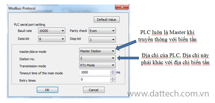
Note: The Baud rate, Data bit, Stop bit, Parity check, and Station no. settings in AutoStation must match those in the VFD.
1.3. After configuring the communication parameters for Ports 0 and 1 of the PLC, create a simple communication program as follows:
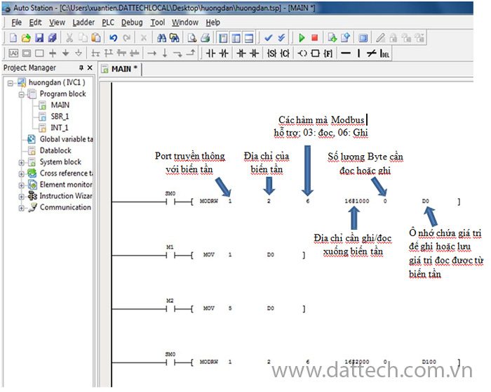
Explanation:
Network 4: Set the speed for the frequency inverter through data memory D100
Network 3: M2 ON, Mov the value 5 into data memory D0 (Stop the VFD)
Network 2: M1 ON, Mov the value 1 into data memory D0 (Run the VFD)
Network 1: Control start/stop of the VFD via Modbus, with D0 as the data memory holding the value to be written to the VFD. If D0 = 1, the VFDr runs; if D0 = 5, the VFD stops. (Refer to the INVT VFD manual for communication details).
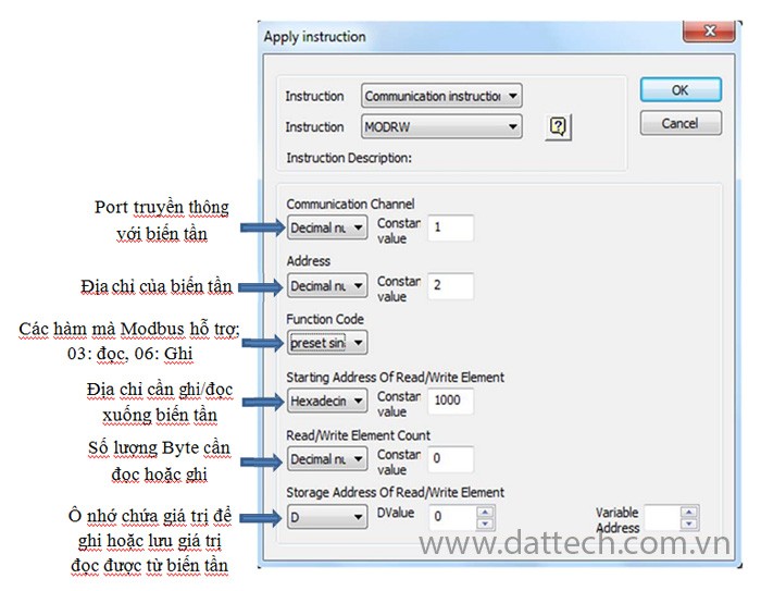
The MODRW instruction in the program is used to read/write values from/to the VFD, with the command structure as follows:
Step 2: Create a Simple Interface on the HMI
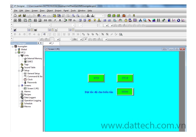
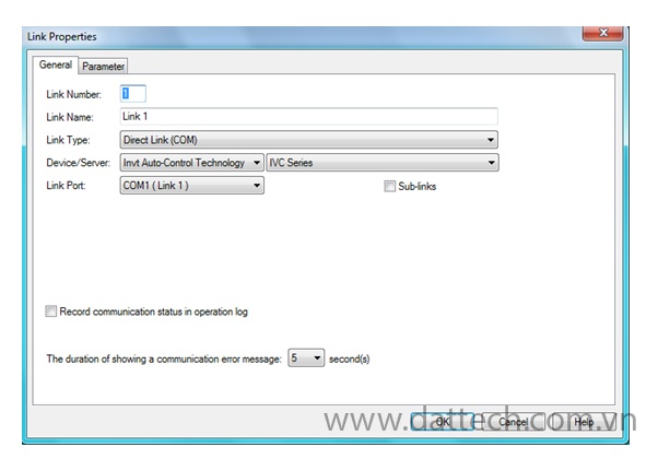
After creating a simple interface using VT Designer software, configure the parameters for HMI to communicate with the PLC. In the Project Manager window, go to Link -> Link 1, and the Link Properties window will appear:
Select Tab Parameter:
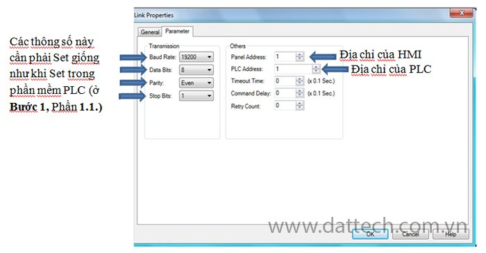
Once the settings are done, click OK.
Step 3: Configure VFD Parameters
P0.01 = 2 Select RUN/STOP through Modbus communication
P0.07 = 7 Select the source to set the speed through Modbus communication
PC.00 = 02 Set the address of the VFD to 2
PC.01 = 4 Choose the communication speed as 19200 bps (Baud rate)
PC.02 = 1 Select the frame as 8, E, 1


