Performing automatic motor parameter detection function for GD35 VFD (MOTOR PARAMETERS AUTOTUNING)
After connecting the power section and completing encoder setup, Autotuning with GD35 is carried out with following steps:
Step 1: Reset all settings to default by setting P00.18=1.
Step 2: Set P00.03 (Max Frequency) and P00.04 (Upper Frequency Limit). Set these two parameters equal to or greater than rated frequency indicated on motor label. If motor does not have user-defined frequency information, enter values that are sufficiently high.
Step 3: Set P00.00=2, allowing VFD to run. Check for any unusual behavior.
Step 4: Set P02.00=0 (motor asynchronous), P02.00=1 (motor synchronous). Enter the motor’s label parameters accurately into parameter group P02.01~P02.05 (for asynchronous motors) or P02.15~P02.19 (for synchronous motors) before proceeding. Entering incorrect values may result in inaccurate parameter detection, affecting VFD’s performance with motor.
Users should remove any load to perform the Autotuning. Autotuning helps VFD better understand motor, resulting in improved control.
 1")
1. Dynamic Autotuning (motor rotates during tuning):
Motor must not be connected to any load, including gearboxes, pulleys, or belts. Ensure that motor was stationary before performing tuning.
Set acceleration and deceleration times to be suitable for mechanical inertia of motor to prevent overcurrent or overvoltage errors during autotuning process (it is advisable to use default values).
The process is carried out as follows:
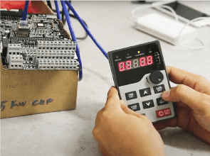
- Set P00.15 then press DATA/ENT button, LED will display “-TUN-” and blink.
- Press RUN button to start the Autotuning process, “RUN/TUNE” LED will blink , LED will display “TUN-0”, “TUN-1”, “TUN-2”, indicating that the motor is stationary.
- After a few seconds, motor will start running, LED will display “TUN-3”.
- After a few minutes, LED will display “-END-”, indicating the completion of the Autotuning process. Motor parameters from P02.06~P02.10 (for asynchronous motors) or P02.20~P02.23 (for synchronous motors) will be updated automatically, and VFD will return to a stopped state.
- During the tuning process, press STOP/RST to cancel the parameter autotuning.
Note: Only RUN/STOP mode via keypad can control autotuning process. P00.15 will automatically reset to 0 when autotuning process is completed or canceled.
2. Static Autotuning (motor remains stationary during tuning):
If it’s not possible to remove the load (including gearboxes, pulleys, or belts), static autotuning is required.
The procedure is identical to dynamic tuning process, but set P00.15 to 2 before pressing the DATA/ENT button. The key difference is that motor does not run during this process.
Note: No-load torque and current intensity cannot be measured in static tuning mode. To optimize vector control, users may input appropriate values based on experience or use default VFD values.
Step 5: After completing the autotuning process, proceed to enter encoder parameters. Set P20.01=??? pulses.
Step 6: Set P00.10=10Hz, P00.00=2, and allow VFD to run. Check the frequency value read by VFD from the encoder in parameter P18.00. If this value is 10Hz, it’s correct. If it’s -10Hz, it means the encoder direction is reversed. To reverse the encoder direction, set P20.02=01. If the value in parameter P18.00 is different from 10Hz, you may need to re-enter encoder pulse count in parameter P20.01 and motor parameters (number of pole pairs for synchronous motors in P02.17, motor speed for asynchronous motors in P02.03).
Step 7: After completing the first six steps, set P00.00=3 (closed-loop control with the encoder). Configure the logic and fine-tune the performance as needed.