Supervision and Simulation Method for Optimal System Display on HMI Screen
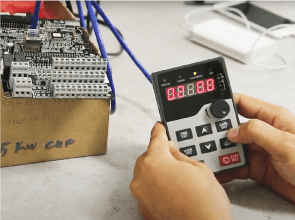
HMI (Human Machine Interface) is a communication device between design operators and machinery. As automation systems become more prevalent, the requirements for internal display and control have become more crucial than ever. This allows equipment operators to simply press virtual buttons on the HMI screen to control or display parameters.
INVT’s HMI, with its compact design, efficiently utilizes space in factories where control space is limited. Furthermore, its touch-based design eliminates the need for keyboards, mice, and cables, enhancing aesthetics and user-friendliness.
INVT’s HMI uses the user-friendly VT Designer software, equipped with all the necessary tools to create the most effective display interface, such as creating dynamic interfaces to simulate system operations.
The purpose of creating a dynamic interface to simulate system on HMI display using INVT’s VT Designer software’s internal memory is to make system representation on HMI screen more vivid, realistic, and easy to monitor compared to a static interface.
For example, in the case of a conveyor belt transporting containers to a waiting position for tank filling, HMI display includes graphs monitoring movement of water inside tank.
1. Program Application
This simulation program is created for following purposes:
- Guide designers on how to create a simulation program on HMI display using VT Designer’s internal memory, replacing memory blocks in the PLC.
- Simulate systems through small applications to help designers understand basic steps to apply and develop other applications in industrial production line systems.

Components include:
- Water supply pipes to tank.
- Water tank.
- Graphical representation of water level in tank.
- Conveyor belt.
- Switch buttons between interface pages.
2. Challenges Presented
- Identifying which object is active at any given time.
- Creating a simulation of system’s operation cycle without using PLC memory.
- Generating a flowing effect in water supply pipes.
- Ensuring conveyor belt transports containers to the correct waiting position.
- Switching between interface pages.
- Creating fluid flow animations in the tank.
- Designing graphs to represent changes in water level over time.
3. Solutions:
All the challenges mentioned above will be addressed in detail in the following tutorials:
- Creating graphical representations of the system on HMI interface screen.
- Simulating movement of water level in tank through HMI display.
- Generating a flowing effect in water supply pipes on HMI screen.
- Creating multiple interface pages on HMI screen.
- Writing a Macro program.