Troubleshooting Guide for Some Errors in INVT GD200A VFD
To ensure stable and safe operation of VFD, users must carefully read the user manual, install it correctly, and strictly adhere to technical warnings. In theory, if the correct setup procedures are followed, incidents are rare. However, in practical operation, due to various subjective or objective factors, VFDs from any manufacturer may encounter some issues.

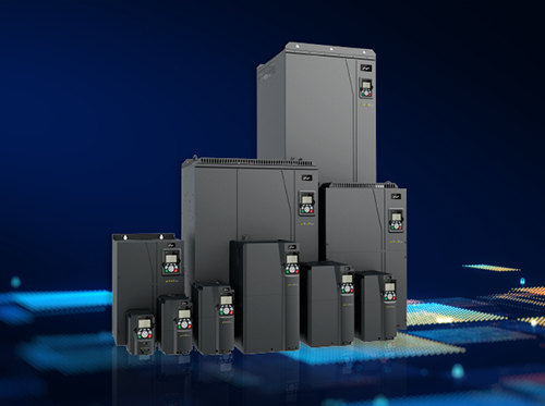
So, what are the common warning errors that VFDs often encounter, and how can they be resolved? In this article, DAT will use the error code table of GD200A VFD, a high-performance versatile VFD from INVT, as an example for analysis. In reality, GD200A series VFD is a robust and powerful high-performance VFD designed to operate even in dusty and humid environments. It incorporates outstanding safety features, making it a rare candidate for encountering malfunctions.
Overall, while VFDs come in various power ranges and from different manufacturers, their operating principles are similar. Therefore, this article should be somewhat beneficial for cases involving VFDs from other brands facing similar issues.
| Error Code | Error Type | Cause | Solution |
|---|---|---|---|
| OUt1 | U-phase IGBT Error | – Case 1: The VFD reports an OUT error upon power-up: + Power board fault in the driver circuit. + Control board malfunction. – Case 2: The VFD reports an error after starting operation: + IGBT module is damaged. + Improper grounding. + Motor malfunction (very rare). + VFD experiences a sudden power loss. |
– Test and check IGBT. – Verify if the grounding method is correct. – Reconnect the IGBT connection cable. – Contact the supplier. |
| OUt2 | V-phase IGBT Error | ||
| OUt3 | W-phase IGBT Error | ||
| OC1 | Overcurrent during acceleration | 1. When VFD is not connected to motor: – IGBT module is damaged. – Output phase is grounded. – VFD’s current detection circuit is faulty. 2. When VFD is already connected to motor: – VFD power rating is not suitable for motor power rating. – Acceleration time is too short or motor parameters are incorrectly set. – Overloaded load. – Motor insulation failure or motor wiring to the VFD is grounded. – VFD’s current detection circuit is faulty. |
1. Inspect the insulation of output phases to ground, and contact supplier. 2. In the error history parameter group, check the current value at the time of error and compare it with VFD’s rated current value: a. If the recorded value is greater than VFD’s rated current value: – Check if VFD power rating matches the load, verify if the load is jammed, reduce the load, and then retry. – Extend the acceleration time accordingly. – Perform autotuning of motor parameters, try selecting Sensorless Vector control mode for VFD. – Contact the supplier. b. If the recorded value is smaller than VFD’s rated current value: – Inspect motor and lead wire insulation. – Try using this VFD to control another motor with the same power rating, or vice versa, to see if the error occurs to eliminate potential causes. – Contact supplier. |
| OC2 | Overcurrent during deceleration | ||
| OC3 | Overcurrent during constant-speed operation | ||
| OV1 | Overvoltage during acceleration | DC BUS voltage higher than the allowable upper limit: higher than 450V for 220V rated voltage and higher than 800V for 380V rated voltage. – Case 1: Occurs during power supply + Supply voltage is too high. + VFD displays incorrect DC BUS voltage, mostly due to a faulty power board. – Case 2: Occurs when VFD controls loads with high inertia (centrifuge, crane, lifting and lowering equipment, etc.) + Deceleration time is too short. + An external force is pushing or pulling motor. + The motor has a problem. + The connection cable between VFD and motor is too long. |
– Extend the deceleration time accordingly. – Share the DC BUS with another VFD. – Use discharge resistors (with DBU if VFD has high power). – Replace with a suitable motor. – Install a reactor every 50 meters of cable length. |
| OV2 | Overvoltage during deceleration | ||
| OV3 | Overvoltage during constant-speed operation | ||
| UV | DC bus voltage too low | DC bus voltage lower than the allowed lower limit: below 180V for 220V rated voltage and below 350V for 380V rated voltage. – Case 1: Due to excessively low supply voltage, running VFD with a heavy load causes a voltage drop on DC BUS: + Insufficient power supply capacity. + Undersized wiring. + Large power load sharing the same power source, causing a voltage drop during startup. – Case 2: The bypass contactor does not close when power is supplied, so when there is a run command, DC BUS voltage drops on the charging resistor, or contactor closes but drops when VFD receives a run command: + Faulty contactor. + Faulty power board. + Faulty fan. + Control board or power board issues (very rare). |
– Case 1: + Increase power supply capacity + Replace with larger wiring. + Use soft-start methods for large power loads sharing the same power source. – Case 2: + Listen to see if the contactor closes when power is supplied. If it doesn’t close, the power board or contactor may be faulty. + Listen if contactor releases when there is a run command. If it does, check fan; it may be malfunctioning. |
| OL1 | Motor overload | Occurs when the output current of VFD is greater than the current value set in P02.05. – The motor is overloaded due to being stuck or selecting an inappropriate power rating. – The motor current parameters and motor overload protection settings are not suitable. – Insufficient power supply voltage. – VFD is faulty. |
– Check and reduce the load. – Check the supplied power voltage. – Adjust the parameters to be appropriate. |
| OL2 | VFD overload | – VFD power rating is not sufficient. – Inappropriate parameter settings. – The load is too heavy, stuck, or motor is faulty. |
– Check and select an VFD with a higher power rating. – Check and adjust the parameters: operating mode, V/F curve, torque compensation, speed feedback before starting, acceleration time, DC braking current intensity before starting and stopping… – Recheck the load. |
| OL3 | Electrical overload | The operation principle is similar to an electronic thermal relay. When enabling this function, users can set the current threshold for fault alarm and the fault alarm delay time. | Check the load and the current threshold settings, as well as the fault alarm delay time. |
| SPI | Loss of input phase. | – Power supply phase failure. – Faulty power supply switching devices for VFD (CB, contactor, ACB switch…). – Open circuit in the power supply cables for VFD. – Loose connections on the input power terminals (R, S, T). – Faulty input phase detection board for VFD. – Faulty control board or power board (very rare). |
– Use a voltmeter to check the input power supply voltage. – Inspect the power supply cables and switching devices for VFD. – Clean the contact points and tighten the input power terminals of VFD. |
| SPO | Loss of output phase | – Case 1: Motor not connected to VFD. – Case 2: Motor connected to VFD. + Open circuit in the cables connecting VFD to motor. + Faulty motor. + Cables connecting VFD to motor are too long. |
– Case 1: Run VFD at 50Hz and use a voltmeter to measure the voltage of the 3-phase output to check if they are balanced. + If the 3-phase voltages are balanced, the issue is in the output voltage sensing circuit. + If the 3-phase voltages are not balanced, the issue is in IGBT drive circuit. – Case 2: + Check and replace cables or motor if necessary. + Install a reactor for every 50 meters of cable length. |
| OH1 | Overheating of the control board | 1. VFD’s cooling fan is not running or is damaged, air vents are blocked. 2. The ambient temperature is too high. 3. Running at a high overload for an extended period. 4. VFD reports incorrect temperature. |
– Clean the ventilation slots of VFD. – Replace the cooling fan. – Adjust the carrier frequency (temporary solution, not recommended). – Contact supplier. |
| OH2 | Overheating of IGBT | ||
| EF | External circuit fault | External interference. | Check the input from external devices. |
| CE | Communication error | 1. Inappropriate communication speed 2. Communication cable fault 3. Incorrect communication address 4. Interference affecting communication |
1. Check the Baud rate 2. Check the communication cable 3. Check the communication address 4. Change or replace the connecting cable to prevent surface interference. |
| ItE | Current detection circuit fault | – Control board is damaged. – Current detection circuit on the power board is damaged. – Current sensor is damaged. – Loose or damaged cable from the power board to the control board. |
– Tighten or replace the control cable. – Replace the current sensor. – Replace the control board or power board. |
| tE | Automatic parameter detection error | 1. Motor of a different power rating. 2. Incorrectly set motor rating parameters. 3. Excessive offset between automatic detection parameters and standard parameters. 4. Exceeded automatic detection time. |
1. Replace VFD. 2. Reset the motor parameters according to the label. 3. Run motor without load and perform re-identification. 4. Recheck motor and reconfigure parameters. 5. Verify the upper frequency limit, which should be set to 2/3 of the rated frequency. |
| EEP | EEPROM error | 1. Read/Write control parameters error. 2. EEPROM is damaged. |
1. Press STOP/RESET to reset. 2. Replace the control panel. |
| PIDE | PID Feedback Loss | 1. Loss of PID feedback signal. 2. Open circuit in PID feedback power supply. |
1. Check the PID feedback power supply. 2. Inspect the PID feedback signal wires. |
| bCE | Brake Error | 1. Brake unit malfunction. 2. Brake resistor is faulty. |
1. Check the brake unit and replace it if necessary. 2. Increase the brake resistor. |
| ETH1 | Ground Short Circuit 1 Error | 1. Output of VFD is short-circuited to ground. 2. Error occurred in the current detection circuit. 3. There is a discrepancy between the actual motor power setting and VFD. |
1. Check the motor connections for any anomalies. 2. Replace Hall board. 3. Replace the main control panel. 4. Reconfigure the motor parameters accurately or replace with a suitable VFD. |
| ETH2 | Ground Short Circuit 2 Error | 1. Output of VFD is short-circuited to ground. 2. Error occurred in the current detection circuit. |
1. Check the motor connections for any anomalies. 2. Replace the Hall board. 3. Replace the main control panel. |
| dEu | Speed Deviation Error | Load is too heavy or changes abruptly. | 1. Check the load and ensure it’s operating normally. 2. Increase the deceleration time. 3. Check the control parameters. |
| STo | Parameter Calibration Error | 1. Incorrect control parameters for the synchronous motor. 2. Incorrect auto-tuning parameters. 3. VFD is not connected to motor. |
1. Check the load and ensure it’s operating normally. 2. Verify that the control parameters are set correctly. 3. Increase the calibration detection time. |
| END | Factory Setting Runtime Error | The actual runtime of VFD exceeds the runtime set by the manufacturer | Contact the manufacturer and adjust the runtime as needed |
| PCE | Keypad Communication Error | 1. The keypad connecting cable is damaged. 2. The keypad connecting cable is too long and affected by interference. 3. Communication circuitry between the keypad and the main circuit is faulty. |
1. Check the keypad cable for any damage. 2. Examine the environment and mitigate interference. 3. Update the software and consult the distributor if necessary. |
| DNE | Parameter Download Error | 1. The keypad connecting cable is damaged. 2. The keypad connecting cable is too long and affected by interference. 3. Communication circuitry between the keypad and the main circuit is faulty. |
1. Inspect the keypad cable to ensure there are no issues. 2. Check the environment and address any interference. 3. Replace the hardware and consult the distributor if needed. 4. Retry data storage. |
| LL | Low Voltage Error | VFD will generate a no-load warning compared to the set value. | Check the load and the no-load warning point. |
Additionally, if you encounter any technical issues that you cannot resolve, please contact DAT’s technical support department or call the HOTLINE at 1800 6567 (toll-free) for immediate assistance.