Guide to Communicating between INVT IVC Series HMI and PLC via Internet
With the remarkable development of Internet, monitoring, programming, and troubleshooting systems over Internet offer numerous advantages to users.
1. Introduction:
The significant growth of Internet has brought substantial benefits to users by enabling remote monitoring, programming, and maintenance of systems over Internet. In this guide, we will outline the steps for establishing communication between an HMI and INVT IVC Series PLC over Internet.
2. Required Equipment and Software:
- INVT PLC IVC1/IVC2-xxx.
- Autostation: Programming software for IVC1/IVC2-xxx.
- INVT Module IVCS – EPM, responsible for converting Modbus RTU to Modbus TCP/IP.
- HMI: INVT VTxxx – H1ET, equipped with an Ethernet 10/100Mb port.
- VT Designer: Programming software for INVT HMI.
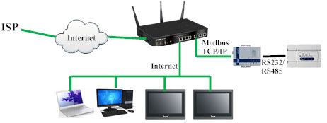
- Ethernet cables, Router, and an ADSL Internet connection.
- Net – Config software, used to configure IP address for Module IVCS – EPM.
3. Step-by-Step Instructions:
Step 1: Connect INVT IVC1/IVC2-xxx PLC to Module IVCS – EPM using shielded cables. Connect Module IVCS – EPM and INVT HMI to Router using Ethernet cables.
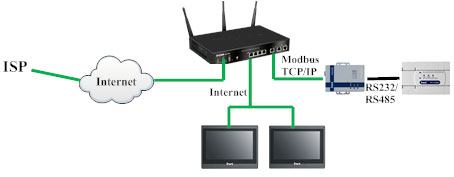
Step 2: Use the Net – Config software to configure the IP address for Module IVCS – EPM and set working mode of Module IVCS – EPM to Modbus TCP/IP slave , as shown in the figure below. Additionally, Module IVCS – EPM can work with RS232 or RS485 standards depending on your choice. Refer to Module IVCS – EPM Manual for detailed configuration steps.
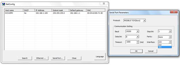
At this point, communication standard for PLC is Modbus TCP/IP, and default working port for PLC on network is Port 502.
Step 3: Power up HMI, select “General” tab, and proceed to configure IP address, subnet mask, and default gateway for HMI.
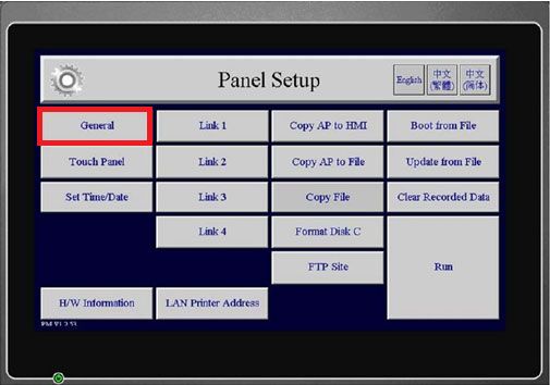
Note: Ensure that IP addresses of HMI, PLC (Module IVCS – EPM), and other components (PC/Laptop) in network do not conflict. The Subnet mask and Default Gateway addresses for all components in network must match. For Default Gateway, consult your network service provider (ISP).
Step 4: On your PC/Laptop, use an Ethernet cable to connect to the Router. Then configure IP address for your PC/Laptop. (You can skip this step as Router can provide automatic IP assignment for PC/Laptop).
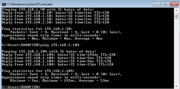
Step 5: On your PC/Laptop, perform a ping test to IP address of Module IVCS – EPM and HMI. If successful, it means that INVT IVC1/IVC2-xxx PLC and HMI are connected. If unsuccessful, revisit Step 2.
Step 6: On your PC/Laptop, open Autostation software, go to the “System block” tab, select “Communication port,” and configure Port 1, communication port for HMI, as follows:
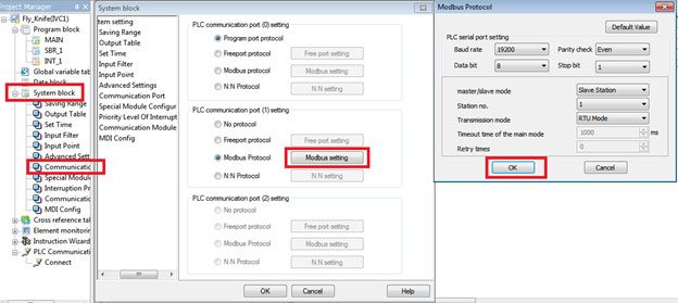
Ensure that communication parameters such as Baud rate, Parity check, Data bit, Stop bit, etc., match the settings of Module IVCS – EPM.
Next, create a simple program for PLC to communicate with HMI. Note that all PLC addresses, such as M0, X0, Y0, D0, etc., must be mapped to Modbus addresses. Refer to the IVC Series Manual, Appendix 7, for more details.

Step 7: Open VT Designer software to program HMI. Configure and create a simple program as follows:
In the “Project Manager” tab, select “Link 1,” and the “Link Properties” window will appear. Choose the “General” tab and configure as follows:
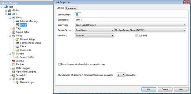
Next, select “Parameter” tab and configure as follows:
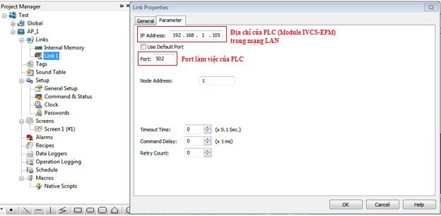
Since working port on PLC’s network is Port 502, configure communication between PLC and HMI through Port 502.
Now, create a simple program to monitor PLC via Modbus TCP/IP.
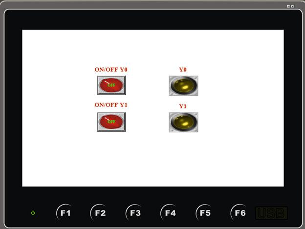
At this point, PLC and HMI can communicate over local area network (LAN) using the Modbus TCP/IP standard.
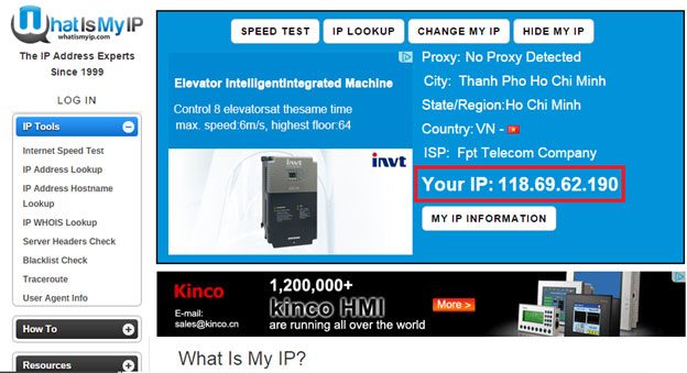
Step 8: To connect INVT IVC1/IVC2-xxx PLC with HMI over wide area network (WAN), connect HMI to a different ISP’s ADSL/Wifi connection. First, check IP address of network to which PLC is currently connected. This is IP address provided by ISP, which can be verified using websites like http://ipaddress.com or http://www.whatismyip.com.
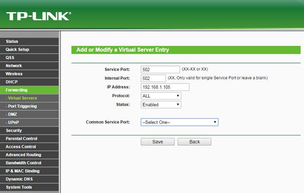
Next, open Port 502 for IP address of INVT IVC1/IVC2-xxx PLC (Module IVCS – EPM) on ADSL Router. The process of opening this port depends on type of router and network service provider.
Then, in VT Designer software, reconfigure IP address for communication with PLC as follows:
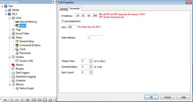
Please note that IP address for communication with PLC in VT Designer configuration should now match IP address provided by ISP.
Step 9: From this point, you can control and monitor INVT IVC1/IVC2-xxx PLC through HMI from anywhere as long as you have an Internet connection.
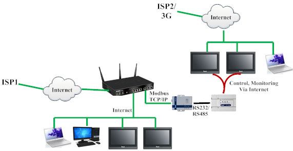
Note: It is essential to regularly update PLC’s IP address because ISP-provided IP address is dynamic and changes continuously. This update can be done using software or manually.
Additionally, users can use VNC Server software to access and control HMI over the Internet. VNC is an independent server that users can download from Internet, and it supports Windows, iOS, and Android operating systems. With VNC Server, users can connect directly to HMI using PCs, laptops, smartphones, tablets, etc., over the Internet.


