How to Wire and Configure INVT GD200A VFD?
This article from DAT will guide you on how to wire and configure parameters for GD200A VFD. Before you begin wiring or configuring VFD, please read the manufacturer’s instructions carefully and adhere to safety regulations.
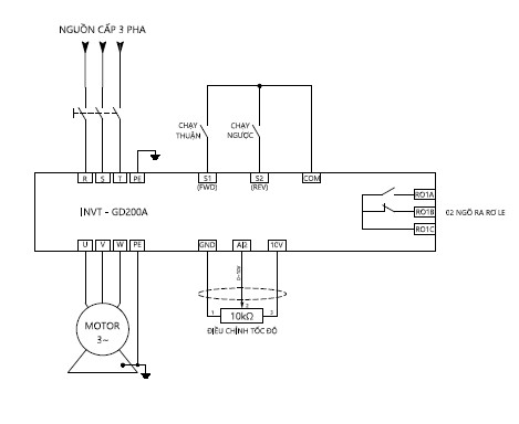
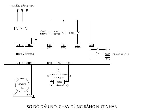
Wiring diagram for start-stop control of GD200A VFD:
Wiring Diagram for Start-Stop Control via Relay
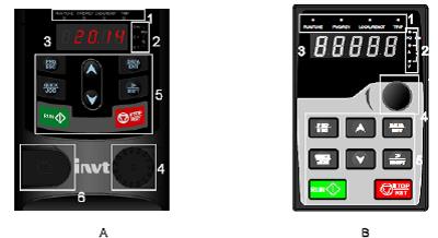
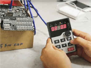
To configure, read data status and change parameters for GD200A VFD, we use the keypad.
The control keys on keypad include:
| Program key | Enter or exit menus from the initial level and quickly change parameters | |
| Enter key | Input or change values and confirm input/changes | |
| UP key | Increase data values or adjust parameters | |
| DOWN key | Decrease data values or adjust parameters | |
| Right-shift key | Shift the displayed value when running/stopping or quickly switch to the parameter to be changed | |
| RUN key | Start VFD when using Keypad mode | |
| Stop/reset key | While running, this key can be used to stop the inverter; this is determined by P7.04. When there is an error, press this key to reset the error. |
|
| Phím Quick | The function of this key is confirmed by P7.02 |
General Function Parameters of GD200A VFD
The function parameters of GD200A VFD are divided into 30 groups (P00~P29) based on their specific functions. Each functional group consists of three menu levels: the function parameter group is at the first level (e.g., P00), the adjustment group is at the second level (e.g., P00.03), and the value setting group is at the third level of the menu (e.g., P00.03 = 50.00Hz).
BASIC PARAMETERS OF GD200A VFD:
| PARAMETER | VALUE | UNIT | DESCRIPTION |
| P00.00 | 2 | V/F Control Mode | |
| P00.01 | 1 | Select Run/Stop Command from Terminal P00.01=0: Select Run/Stop Command from Keypad ( RUN / STOP key) |
|
| P00.03 | 50.00 | Hz | MAX frequency, must be set greater than or equal to motor’s rated frequency |
| P00.04 | 50.00 | Hz | Upper frequency limit |
| P00.05 | 00.00 | Hz | Lower frequency limit |
| P00.07 | 03 | ||
| P00.06 | 02 | Select the speed reference source using an external potentiometer at AI2 input; P00.06=00: Select speed reference source using keypad (6/5) P00.06=01: Select speed reference source using potentiometer on keypad. |
|
| P00.11 | … | Seconds | Acceleration time (time from 0Hz to MAX frequency) |
| P00.12 | … | Seconds | Deceleration time (regenerative time from MAX frequency to 0Hz) |
| P01.18 | 0 | Prohibit running if S1-COM is already connected when powered on P01.18=1: Allow running if S1-COM is already connected when powered on |
|
| P04.01 | 2.0 | % | Start-up torque compensation at low frequency |
| P04.09 | 000.0 | % | Disable slip compensation for motor |
| P05.01 | 1 | S1 Terminal Function: Forward operation | |
| P05.02 | 2 | S2 Terminal Function: Reverse operation | |
| P02.01 | … | kW | Rated power of motor |
| P02.02 | … | Hz | Rated frequency of motor |
| P02.03 | … | RPM | Rated speed of motor |
| P02.04 | … | V | Rated voltage of motor |
| P02.05 | … | A | Rated current intensity of motor |
How to Input Parameters
To input parameters according to the following flowchart:
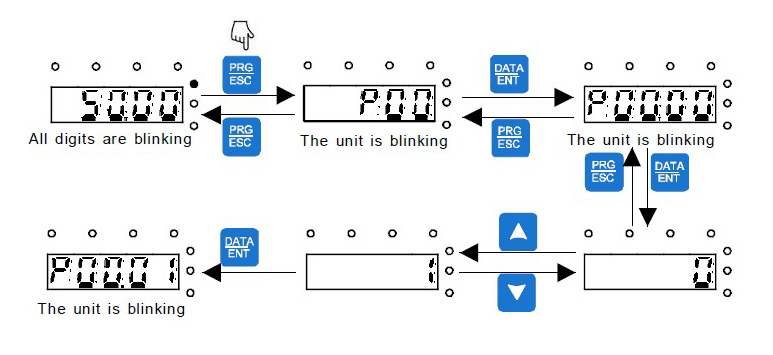
Note:
- The SHIFT key is used to change the display of the set frequency, motor speed, motor current intensity, etc. (The status lights correspond to the displayed data).
- Reset parameters to the manufacturer’s defaults: P00.18 = 1
We hope that through this article, you have learned how to wire and configure INVT GD200A VFD. For any questions or support, please contact DAT via the toll-free hotline 1800 6567.
Additionally, DAT has a network of distributors nationwide. You can contact the one nearest to you. Our team of engineers will provide direct consultation and assist you in resolving your issues as soon as possible.


