The methods of controlling VFDs
In addition to selecting a VFDe that suits the requirements, the method of controlling the VFD will also affect the quality and efficiency of the machinery system operation
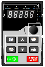
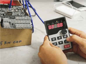
Method 1: Controlling the VFD with start/stop and speed adjustment through a keypad
| Button | Name | Function |
 |
Program key | Access parameter setting groups |
 |
Data entry key | Enter or modify parameter settings |
 |
Up key | Increase the value of parameter settings |
 |
Down key | Decrease the value of parameter settings |
 |
Shift key | Switch display parameters or quickly access the parameter group to be set |
 |
Run key | Start the VFD using the keypad |
 |
Stop key | Stop the VFD using the keypad |
 |
Jog key | Function defined by parameter P07.02 |
Purpose of control:
- Start/stop the VFD via keypad or Terminal
- Adjust the frequency using increase/decrease keys or volume button on keypad
Setting Parameters
| Parameter | Value | Unit of measure | Function |
| P00.00 | 2 | V/F Control Mode | |
| P00.01 | 0 |
P00.01 = 0, function for starting/stopping the VFD via keypad P00.01 = 1, function for starting/stopping the VFD via terminal |
|
| P00.03 | 50.00 | Hz | Max Frequency |
| P00.04 | 50.00 | Hz | Upper Frequency Limit |
| P00.05 | 00.00 | Hz | Lower Frequency Limit |
| P00.06 | 0 |
P00.06 = 0, frequency adjustment via increase/decrease keys P00.06 = 1, frequency adjustment via volume button on the VFD |
|
| P00.11 | … | Seconds | Acceleration Time |
| P00.12 | … | Seconds | Deceleration Time |
| P04.01 | 2.0 | % | Startup Torque Compensation |
| P04.09 | 0.0 | % | Slip Compensation Disabled |
| P05.01 | 1 | Function S1 for Forward Run if P00.01 = 1 | |
| P05.02 | 2 | Function S2 for Reverse Run if P00.01 = 1 | |
| P02.01 | … | kW | Motor Rated Power |
| P02.02 | … | Hz | Motor Rated Frequency |
| P02.03 | … | Rpm | Motor Rated Speed |
| P02.04 | … | V | Motor Rated Voltage |
| P02.05 | … | A | Motor Rated Current |
Method 2: Multi-speed VFD Control
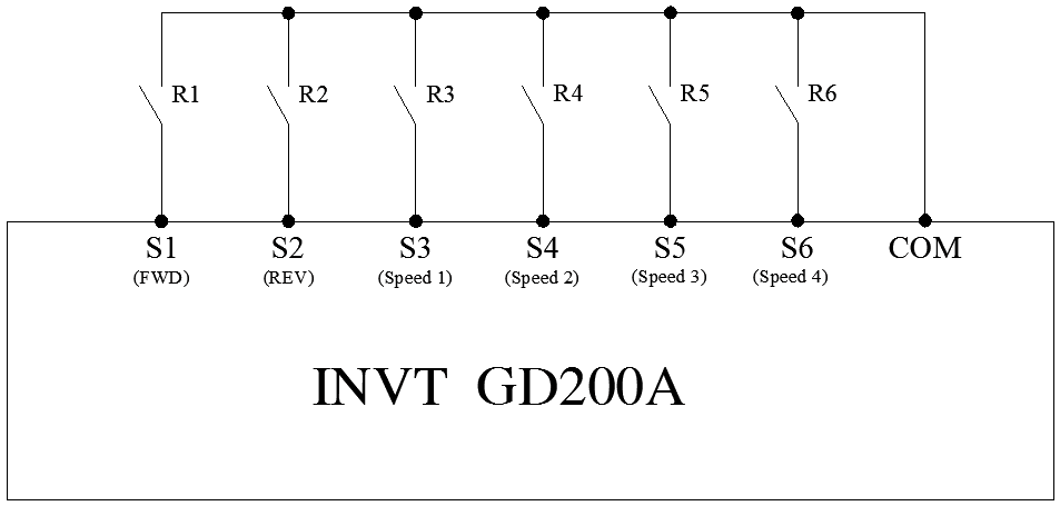
INVT VFDs allow the motor to run at 16 different speeds through 4 control signals on Terminal.
Multi-speed function is used based on the machinery’s technological requirements.
Multi-speed control signal table
|
Signal/ Speed Level |
Terminal Speed 1 (Function16) |
Terminal speed 2 (Function 17) |
Terminal speed 3 (Function 18) |
Terminal speed 4 (Function 19) |
Speed Setting Parameters (%) |
| 0 | OFF | OFF | OFF | OFF | P10.02 |
| 1 | ON | OFF | OFF | OFF | P10.04 |
| 2 | OFF | ON | OFF | OFF | P10.06 |
| 3 | ON | ON | OFF | OFF | P10.08 |
| 4 | OFF | OFF | ON | OFF | P10.10 |
| 5 | ON | OFF | ON | OFF | P10.12 |
| 6 | OFF | ON | ON | OFF | P10.14 |
| 7 | ON | ON | ON | OFF | P10.16 |
| 8 | OFF | OFF | OFF | ON | P10.18 |
| 9 | ON | OFF | OFF | ON | P10.20 |
| 10 | OFF | ON | OFF | ON | P10.22 |
| 11 | ON | ON | OFF | ON | P10.24 |
| 12 | OFF | OFF | ON | ON | P10.26 |
| 13 | ON | OFF | ON | ON | P10.28 |
| 14 | OFF | ON | ON | ON | P10.30 |
| 15 | ON | ON | ON | ON | P10.32 |
VFD Connection Diagram
Setting Parameters
| Parameter | Value | Unit of measure | Function |
| P00.00 | 2 | V/F Control Mode | |
| P00.01 | 0 |
P00.01 = 0 function for starting/stopping the VFD via keypad P00.01 = 1 function for starting/stopping the VFD via terminal |
|
| P00.03 | 50.00 | Hz | Max Frequency |
| P00.04 | 50.00 | Hz | Upper Frequency Limit |
| P00.05 | 00.00 | Hz | Lower Frequency Limit |
| P00.06 | 6 | Select multi-speed mode | |
| P00.11 | … | Seconds | Acceleration Time |
| P00.12 | … | Seconds | Deceleration Time |
| P04.01 | 2.0 | % | Startup Torque Compensation |
| P04.09 | 0.0 | % | Slip Compensation Disabled |
| P05.01 | 1 | Function S1 for Forward Run if P00.01 = 1 | |
| P05.02 | 2 | Function S2 for Reverse Run if P00.01 = 1 | |
| P05.03 | 16 | Function S3: Speed Control Signal 1 | |
| P05.04 | 17 | Function S4: Speed Control Signal 2 | |
| P05.05 | 18 | Function S5: Speed Control Signal 3 | |
| P05.06 | 19 | Function S6: Speed Control Signal 4 | |
| P10.02 | … | % | Percentage Speed Setting 0 |
| P10.04 | … | % | Percentage Speed Setting 1 |
| P10.06 | … | % | Percentage Speed Setting 2 |
| P10.08 | … | % | Percentage Speed Setting 3 |
| P10.10 | … | % | Percentage Speed Setting 4 |
| P10.12 | … | % | Percentage Speed Setting 5 |
| P10.14 | … | % | Percentage Speed Setting 6 |
| P10.16 | … | % | Percentage Speed Setting 7 |
| P10.18 | … | % | Percentage Speed Setting 8 |
| P10.20 | … | % | Percentage Speed Setting 9 |
| P10.22 | … | % | Percentage Speed Setting 10 |
| P10.24 | … | % | Percentage Speed Setting 11 |
| P10.26 | … | % | Percentage Speed Setting 12 |
| P10.28 | … | % | Percentage Speed Setting 13 |
| P10.30 | … | % | Percentage Speed Setting 14 |
| P10.32 | … | % | Percentage Speed Setting 15 |
| P02.01 | … | kW | Motor Rated Power |
| P02.02 | … | Hz | Motor Rated Frequency |
| P02.03 | … | Rpm | Motor Rated Speed |
| P02.04 | … | V | Motor Rated Voltage |
| P02.05 | … | A | Motor Rated Current |
Formula for converting percentage speed setting to operating frequency of the VFD:
Where:
- F: Operating frequency of the VFD
- P: Percentage speed setting
- 03: Upper frequency limit of the VFD
Method 3: Controlling the VFD via Modbus Communication
- VFDs offer various methods for start/stop control and speed control, among which control through communication using Modbus protocol is possible.
- The Modbus communication protocol has two types, ASCII and RTU, and in a Modbus network, there can be one master and multiple slaves.
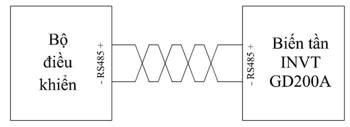
- In GD200A series, connection is established through two terminals, RS485+ and RS485-, so twisted pair cables should be used.
Wiring diagram
Purpose of control: Communication of start/stop commands and speed to the VFD
Setting Parameters
| Parameter | Value | Unit of measure | Function |
| P00.00 | 2 | V/F Control Mode | |
| P00.01 | 2 | Function of the VFD to start/stop via communication | |
| P00.03 | 50.00 | Hz | Max Frequency |
| P00.04 | 50.00 | Hz | Upper Frequency Limit |
| P00.05 | 00.00 | Hz | Lower Frequency Limit |
| P00.06 | 8 | Function of speed adjustment via communication | |
| P00.11 | … | Seconds | Acceleration Time |
| P00.12 | … | Seconds | Deceleration Time |
| P04.01 | 2.0 | % | Startup Torque Compensation |
| P04.09 | 0.0 | % | Slip Compensation Disabled |
| P14.00 | 1 | Modbus Slave Address | |
| P14.01 | 4 | Modbus Communication Speed 19200 | |
| P14.02 | 1 | Modbus Transmission Frame (E,8,1) | |
| P02.04 | … | V | Motor Rated Voltage |
| P02.05 | … | A | Motor Rated Current |
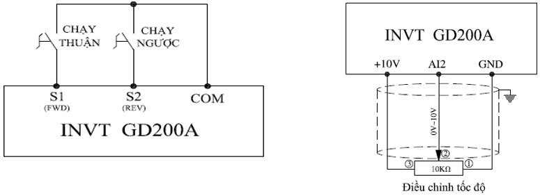
Method 4: Controlling the VFD for start/stop and speed adjustment through an external potentiometer
Wiring diagram
Setting Parameters
| Parameter | Value | Unit of measure | Function |
| P00.00 | 2 | V/F Control Mode | |
| P00.01 | 1 | Function for starting/stopping the VFD via terminal | |
| P00.03 | 50.00 | Hz | Max Frequency |
| P00.04 | 50.00 | Hz | Upper Frequency Limit |
| P00.05 | 00.00 | Hz | Lower Frequency Limit |
| P00.06 | 2 | Function of frequency adjustment through an external potentiometer | |
| P00.11 | … | Giây | Acceleration Time |
| P00.12 | … | Giây | Deceleration Time |
| P04.01 | 2.0 | % | Startup Torque Compensation |
| P04.09 | 0.0 | % | Slip Compensation Disabled |
| P05.01 | 1 | Function S1 for Forward Run | |
| P05.02 | 2 | Function S2 for Reverse Run | |
| P02.01 | … | kW | Motor Rated Power |
| P02.02 | … | Hz | Motor Rated Frequency |
| P02.03 | … | Rpm | Motor Rated Speed |
| P02.04 | … | V | Motor Rated Voltage |
| P02.05 | … | A | Motor Rated Current |
For more detailed information, please contact the hotline at 18006567 (toll-free) for quick assistance.


