Control Modes in VFDs
To fully experience intelligent and flexible features of a VFD, it’s essential to understand fundamental control modes of VFDs. This article will provide you with a general overview of V/F control mode, open and closed-loop vector control modes, and torque control modes in VFDs.
1. V/F Control Mode
V/F (Voltage/Frequency) control is basic and widely used control mode in all types of VFDs. It operates on the principle that torque on asynchronous motor’s shaft depends on frequency and voltage ratio of the power supply, aiming to maintain a constant V/F ratio.
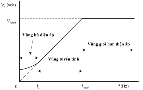
In this mode, the VFD controls the frequency in range of 0Hz to Fmax and corresponding voltage in range of 0V to Vmax. In practice, the relationship between frequency and voltage is divided into three speed ranges:
- From 0Hz to starting frequency (Hz): The input voltage is low, resulting in low starting current, which can lead to insufficient torque for motor starting. Therefore, voltage compensation is applied, resulting in a non-linear V/F ratio.
- From starting frequency (Hz) to rated frequency (Hz): The V/F ratio is linear, and the motor’s torque is stable.
- Above rated frequency (Hz): The voltage is limited to the rated voltage to prevent insulation breakdown between windings. Consequently, the motor’s torque decreases.
For asynchronous motors, there is always a slip factor ‘s’ on motor shaft speed. When motor operates without a load, the slip factor ‘s’ is very low, and motor speed is nearly equal to synchronous speed. When motor operates with a load, ‘s’ becomes significant, and V/F mode may not be accurate. Therefore, slip compensation is applied to improve performance.
2. Open-Loop and Closed-Loop Vector Control Modes in VFDs
Vector control modes, both open-loop and closed-loop, offer higher precision compared to V/F mode.
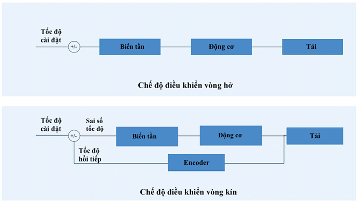
- Open-Loop Vector Control: This method is based on feedback from motor current. The VFD simulates a rotor flux vector and controls frequency and voltage parameters to precisely regulate motor’s speed.
- Closed-Loop Vector Control: This control mode creates a rotor flux vector within motor by using encoder feedback to determine actual motor speed. The VFD adjusts frequency, voltage, and carrier frequency based on encoder signal to accurately control motor’s speed.
3. Torque Control Modes in VFDs
The formula for calculating torque produced by a motor is:
T(Nm) = 9550 x P(kW)/n(rpm)
Where: P is motor power, n is motor speed.
Torque control in VFDs means controlling motor torque precisely according to requirements. To achieve this, the VFD calculates load torque and acceleration/deceleration time to maintain constant power ‘P’. Therefore, torque is inversely proportional to speed, meaning heavy loads run at low speed and light loads run at high speed.
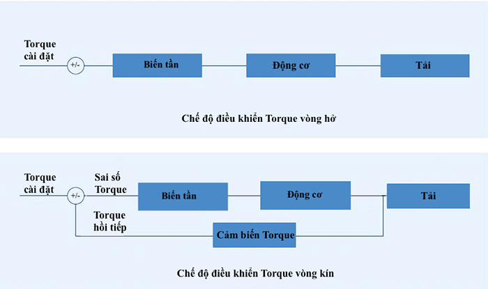
Torque control in VFDs includes two methods: open-loop torque control and closed-loop torque control.
- Open-Loop Torque Control: The VFD uses motor current and voltage feedback to calculate estimated motor torque. It adjusts motor torque based on initial setpoint torque value. However, open-loop torque control may not achieve high accuracy and is suitable for applications with less stringent precision requirements.
- Closed-Loop Torque Control: In this method, the VFD relies on motor current and voltage feedback as well as speed feedback from an encoder. It adjusts motor torque with high precision and is suitable for applications with stringent precision requirements.
For more detailed information, please visit https://dattech.com.vn/ or contact the hotline at 18006567 (toll-free) for quick support and advice.


