Guide on how to create a flowing effect in a simulated pipeline on HMI display screen
One hypothesis that arises is: If an industrial system has many pipelines: oil pipelines, water pipelines, ventilation ducts, smoke pipes, etc., how can we differentiate between these pipelines? And at what point is each pipeline in operation? When does movement of object inside pipeline start and end? INVT’s VT Designer software supports a method to create a flowing effect within pipelines to enhance clarity of simulation process.
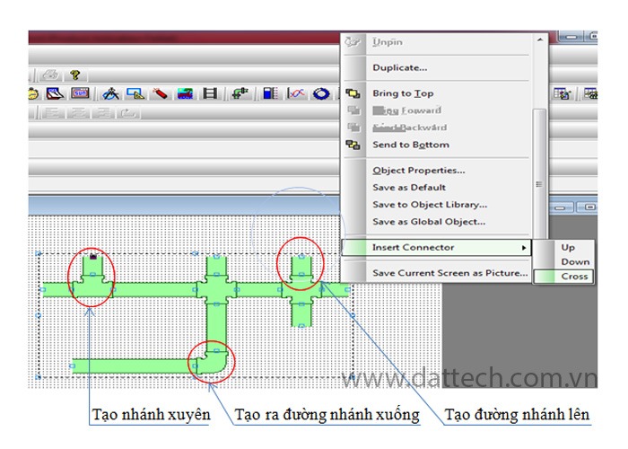
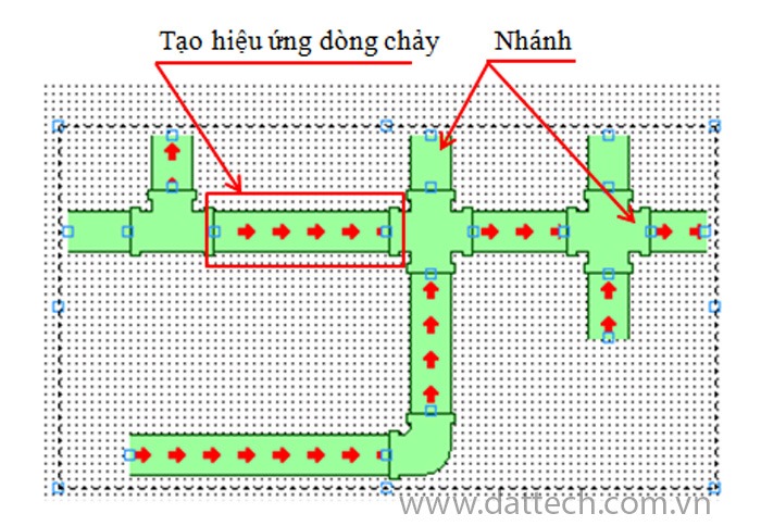
Step 1: Creating Pipelines
Create pipelines by clicking on ‘Pipeline’ icon in toolbar -> create a pipeline -> right-click on pipeline’s location where the designer wants to branch it, either upwards, downwards, or horizontally as per design requirements.
Step 2: Setting Properties for the Object
- Click on created ‘Pipeline’ to modify its properties:
Type : Choose the shape.
Dimension : Object dimensions.
Thickness : Pipeline thickness.
Border color/ body color : Select colors for the object.
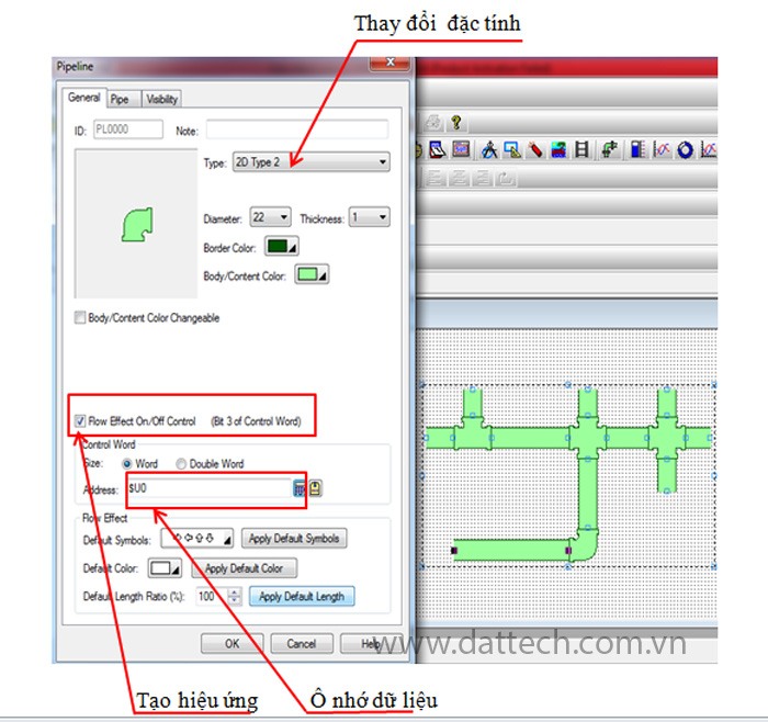
Step 3: Creating the Flowing Effect
Flow effect -> create a memory location to store data $U0. Bit 3 is the bit that controls on/off state of flowing effect. When this bit is set ($U0=08), flow will move as shown below.
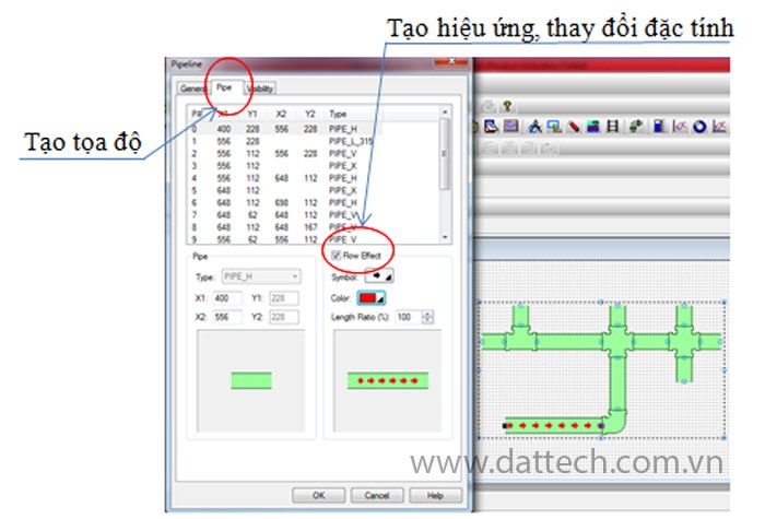
Click tab “pipe” -> Create coordinates.
Check “Flow effect” -> Choose direction of flow arrow, format attributes, and colors.
After completing the above three steps, you will have created a flowing effect according to design requirements when bit 3 of the memory location is set to 1.